In this post I want to cover one element of the work I did to implement a portal renderer. Head over to the repo for a overview of the project and a look at the end result.
First some background on the specifics of how a portal based engine (Duke Nukem 3d, Descent) works, and how it is different to a BSP tree implementation as used by Doom. Whichever way you look at it these are both very old styles of creating a 3D environment for a game but, by making some basic assumptions about the nature of the world, the rendering could be simplied to the point that they would run at reasonable frame rates on an early 90s PC. I’m not at all experienced in 3D rendering so it didn’t seem unreasonable to begin my education with the operation of an early 3D game engine.
Portal based rendering
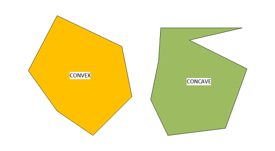
I started with a portal based engine, mainly because that was the focus of the material that gave me the inspiration to start this project Creating a Doom-style 3D engine in C. With portals, the entire ‘world’ is divided into convex polygons. The most important feature of a convex polygon from the point of view of a renderer is that, from any point within the polygon, all wall segments are completely visible. And because no part of any wall can be occluded, there is no need to implement a z-buffer or perform expensive per-pixel visibility tests.
Each wall of a polygon can be defined as either displaying a texture, or being a portal through into another connected polygon.
The process of rendering can therefore be defined as:
- Render textured walls of polygon that the player is in
- For any walls defined as portals, add polygon on the other side to a rendering list
- Render next polygon(s) in list
- Repeat 2 and 3 until there are no more to draw
This description deliberately ignores drawing floors and ceilings, but this is OK because they don’t affect the central principle of how portal engines work. Also, the definition of ‘no more to draw’ is really up to the renderer.
So, the most important piece of information for each polygon (or sector) is, which walls pass through into another sector, and information about what that sector is.
Sectors and wall portals aren’t just used for rendering though. Movement of the player through the world also makes use of this information. When the player approaches a wall its a fairly trivial collision test to determine whether to stop the player at the wall, or let them pass through into the neighbouring sector.
BSP tree rendering
Next we look at the BSP tree mechanism used by the Doom engine. The BSP (or Binary Space Partition) is a tree structure that represents subdivisions of a space into 2 smaller spaces, and when this is applied recursively to a level it can be used to decompose the structure down until the leaves of the BSP tree are convex polygons.
The process for rendering from a BSP tree can be defined as:
- Begin at the root node (representing the entire level space)
- Recurse down through the structure based on which side of the partition line the player position is
- When a leaf (convex polygon) is reached, draw any textured walls
- Unwind recursion, drawing walls
Although performing a BSP traverse is quite different to the portal system, it fulfills the same goal of rendering the walls closest to the player first.
There are a number of advantages and disadvantes to each system. For example, with the BSP tree there is no need to retain information about which sector the player is in, or perform collision tests against sector wall to know when the player moves into a different sector. It is also considered to be a simpler (and therefore almost certainly faster) mechanism for rendering. However, a portal engine has one very important advantage. It is able to support rooms on top of other rooms, and even non-euclidean geometry. This is because each sector in the level is effectively defined by its connections to its neighbouring sectors. Whereas, given a location within in a level, there is only ever a single solution within a 2D BSP tree.
That’s as far as I’m going to go in this post about the different engines used at that time. There is plenty of information out there to cover each technique in far more detail.
How to make portals from a BSP
The whole point of this post, however, is to talk about how to generate a level that is suitable for a portal based renderer, when the starting point is BSP tree based (Doom level). As I already mentioned at the start, the project I was working on was to implement a portal renderer.
But one of the goals I set myself from the very start was that I wanted to be able to render a Doom level. Preferably E1M1, where it all begins! I had the renderer working well, and it was able to load and display a level defined as described above. i.e. convex polygons (sectors) with links to say which sector was on the other side of each portal.
It was time to start reading through the Doom WAD (container) format, which I assumed would be generally similar to the level data I’d already been using. Perhaps a few tweaks to adjust for different vertex scaling and whatever format was used for storing textures. How wrong I was!
In the WAD format, there are elements called sectors. But these are only there to separate sections of the map into areas that have the same underlying settings, such as floor and ceiling height. They certainly don’t fulfill the requirement of being convex polygons.
What to try next
Then we move onto elements in the WAD called sub-sectors. These are definitely convex polygons! .. at least in theory. The result of traversing the 2D BSP tree is arrival at a leaf node that represents a sub-sector (the node literally contains the index for a sub-sector in the WAD). The problem is, because the Doom engine just uses this information for rendering, the sub-sector often only contains the lines of the convex polygon that have a texture attached to them. So you can easily end up with a sub-sector that only explicitly defines 1 or 2 lines of the convex polygon. That doesn’t quite work either then.
All the information has to be there though, it just exists as implied edges within the BSP tree.
The first step then is to take the information already available in a sub-sector definition and, from this, turn it into a fully formed convex polygon. To successfully traverse the BSP tree down to a sub-sector we need to know a position inside the sub-sector. Luckily, we know that a sub-sector must have at least 1 wall explicitly defined so we can just project a normal vector a short way from the mid-point of this wall into the sub-sector.vfVec2 unitNormal = unit(segmentEnd - segmentStart) * normal();
vfVec2 insidePoint = midpoint(segmentStart, segmentEnd) - (unitNormal * 0.01f);
This pretty much guarantees us a position inside the sub-sector, apart from a couple of edge conditions that I’ll mention later. We then traverse the BSP tree, starting with an axis-aligned bounding box surrounding the entire map. At each node of the tree, the bounding area is clipped with the partition line for that BSP node to create a new bounding area.vfPoly boundingPolygon = makeAABB({0.f,0.f}, worldExtent);
while(traverseComplete == false)
{
vfVec2 pLineStart = partitionNode.start;
vfVec2 pLineEnd = partitionNode.end;
vfVec2 clippingPlane = pLineEnd - pLineStart;
// Determine which side of the partition line the inside subsector point is situated
vfVec2 samplePointFromPlane = pLineStart - insidePoint;
r32 samplePointInsidePlane = crossProduct(clippingPlane, samplePointFromPlane);
bool selectRightSide = (samplePointInsidePlane >= 0) ? true : false;
clipPolygonToLine(boundingPolygon, pLineStart, pLineEnd, selectRightSide);
// Travel to the next node in the BSP based on which side of the partition line our
// 'insidePoint' is
partitionNode = (selectRightSide == true) ? partitionNode.rightNode : partitionNode.leftNode;
if (partitionNode.isSubsectorNode)
{
traverseComplete = true;
}
}
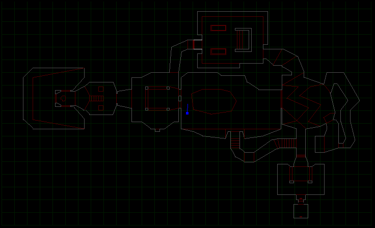
The end result is ‘nearly’ the convex polygon we want. This is a polygon that has been created from all the implicit partition lines of the BSP tree. There is one final step where we also go through any explicitly defined lines from the original sub-sector definition and also clip the polygon to these.
This is the result.
As I mentioned there are a couple of edge conditions that mean this isn’t a perfect solution. The original BSP tree can create some degenerate polygons, which means that some sectors are not properly closed or there are vertexes outside of the normal convex area. The example below shows a polygon with 4 vertexes, but with one vertex colinear with 2 others.
If these do occur they generally exist in very limited areas of the map, and for now they just get discarded. I might come back and fix these one day, seeing as the algorithm already detects occurances.
Fixing everything else
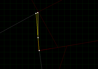
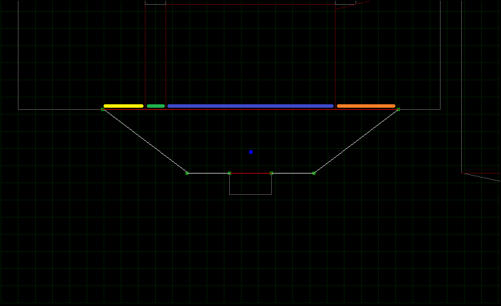
We now have a complete set of convex polygon ‘sub-sectors’ to define the renderable area of the level. And this is where we find the next problem with the data. In the Doom WAD file, actual walls to render are defined by a seg (or segment). A segment defines a line, which is part of the sub-sector, along with details of the texture data that should be rendered on that bit of wall. Because of the way we’ve generated the sub-sector lines by clipping against BSP partition lines, we can end up losing vital information where points on the original sub-sector definition were colinear.
This can be seen below where the segment lines (highlighted in blue) are just part of the generated sub-sector edge.
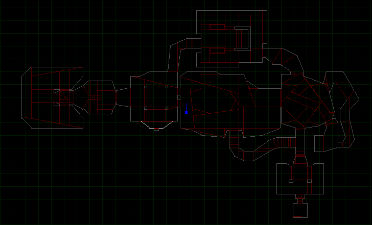
Fortunately, this is quite simple to fix by just adding any vertexes from explicitly defined segment edges to our generated sub-sector polygon. Of course these new vertexes are just added onto the end of the polygon so we need one last step to sort the vertexes into a consistent winding order and remove any duplicates.
We’re one step closer to a working Portal based Doom level! In fact, if all we wanted to do was render the level then actually we’d be almost done. We can simply scan through all of the explicitly defined segment edges for our sub-sector and compare them to the generated walls of our sub-sector. If the vertexes match, give or take some tolerance, then we can associate segments (and therefore textures) with generated walls… and that’s enough information to display our level.
But, we don’t just want to render the level. We also want to be able to move around the level! And for this, as I said at the start, each portal wall needs to store information about the sub-sector that is on the other side of the wall.
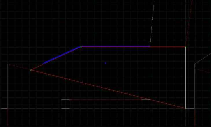
This is when we see another problem with the sub-sectors generated so far. Portal walls that cover more than one sub-sector. In the example below, a single portal wall is connected to 4 possible sub-sectors (each highlighted with a different colour).
In this case, moving from any of the 4 highlighted sub-sectors into the large sub-sector happens to produce the correct result. However, what happens going the other way is undefined. If a wall can only contain a single reference to a sub-sector on the other side of the wall then it’s impossible for the player to travel into 3 of the 4 highlighted sub-sectors. We don’t want complex relationships between sub-sectors, so the only answer is we need more walls! Or more accurately.. more vertexes.
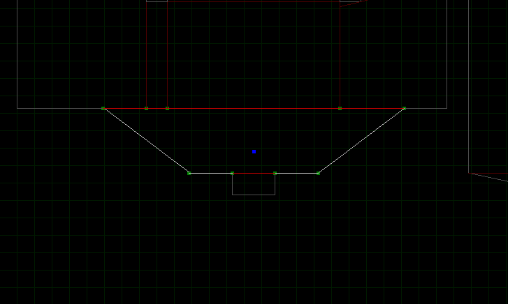
For every wall in the sub-sector we check every vertex (in every other sub-sector of the level) to see if it lies on the wall. If we find a vertex that does lie on the wall, give or take some tolerance, then we add that vertex to the current sub-sector. Repeat that for all vertexes on all sub-sector walls.
The result should be portal walls that always have a 1-1 mapping between 2 connected sub-sectors. See the additional vertexes that have been created.
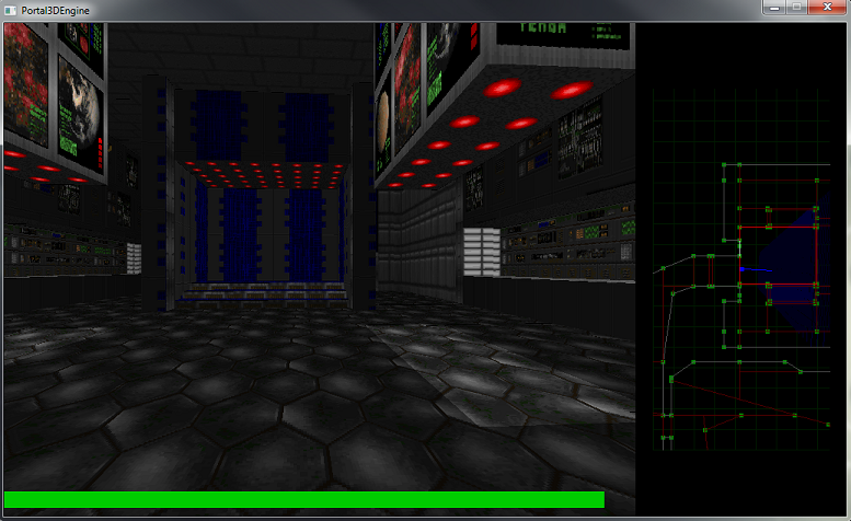
Summary
And that’s about it. All the information is there to allow navigation around the map and the renderer always know which sector (or sub-sector in Doom terminology) the player is in. Also, once segments have been associated with sector walls there is enough information to display the level from the point of view of the player. A Doom level rendered with a Portal Rendering system.
As much as I’d like to finish on that high note, there is one thing that doesn’t quite work. I will probably go back and fix it one day, but for now I’ll just mention it here. The final bit of post-processing, to ensure there are 1-1 relationships on sub-sector walls, occasionally breaks the segment (and therefore texture) association. So, if we’ve placed additional vertexes in a wall, and the original wall has a segment associated with it (defined by the start and end vertex of the original wall) then we have no way to associate them back up again. This doesn’t happen very often, but on occasion you can see a wall with no texture. When you do, this is probably the reason.